Morpheus
Morpheus was a late-2008 mechanical study for an integrated Blu-ray system in Kaleidescape’s Megalon program. The design brief called for maximum reuse of KS-100 mechanics while adding new optical-drive and connector requirements. It was an exercise in deciding where an existing product architecture could carry forward and where new hardware would force a change.
I developed the mechanical layouts and briefs with the hardware team. Adrian Fung coordinated the electronics architecture, Greg Curry developed connector and board requirements, Vince Di Lello handled PCB layout, and Nathan Forster developed thermal concepts. The November project-update agenda assigned mechanical architecture to me, thermals to Nathan, and the hardware architecture and schedule to Adrian.
Setting the reuse boundary
The October meeting set a starting envelope of no more than two rack units unless the team made a deliberate decision to exceed it. That was a design constraint, not a measured production size. My assignments included a Morpheus layout snapshot and a mechanical schedule that connected prototype milestones to the larger program.
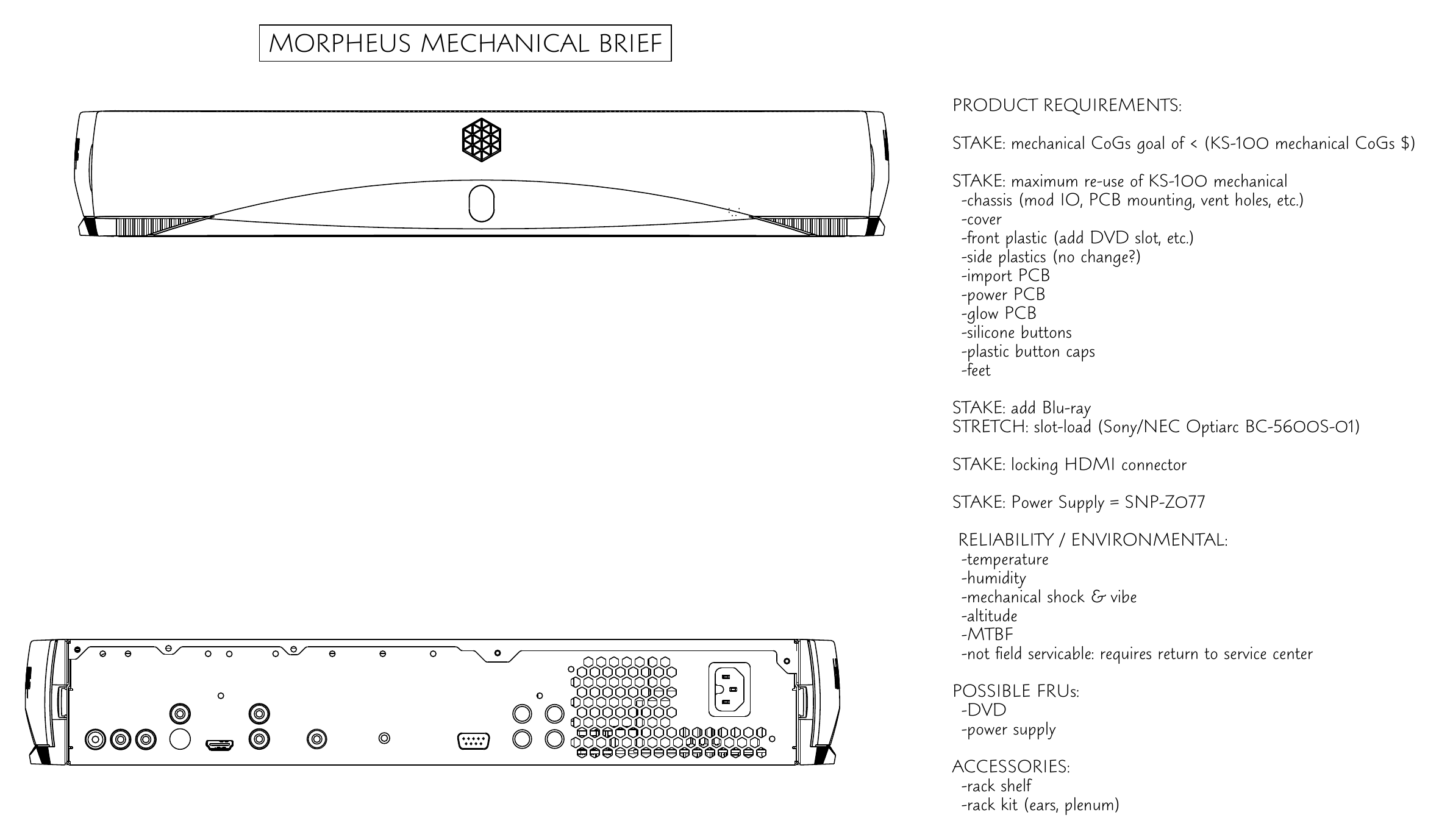
The mechanical brief separated requirements from stretch ideas. It called for lower mechanical cost than the KS-100 and maximum reuse of the chassis, cover, front and side plastics, interface boards, buttons and feet. Blu-ray capability, a locking HDMI connector and a named power supply were baseline requirements. A slot-loading optical drive remained a stretch option. The distinction mattered because each new opening, board position or vent could reduce the value of reuse.
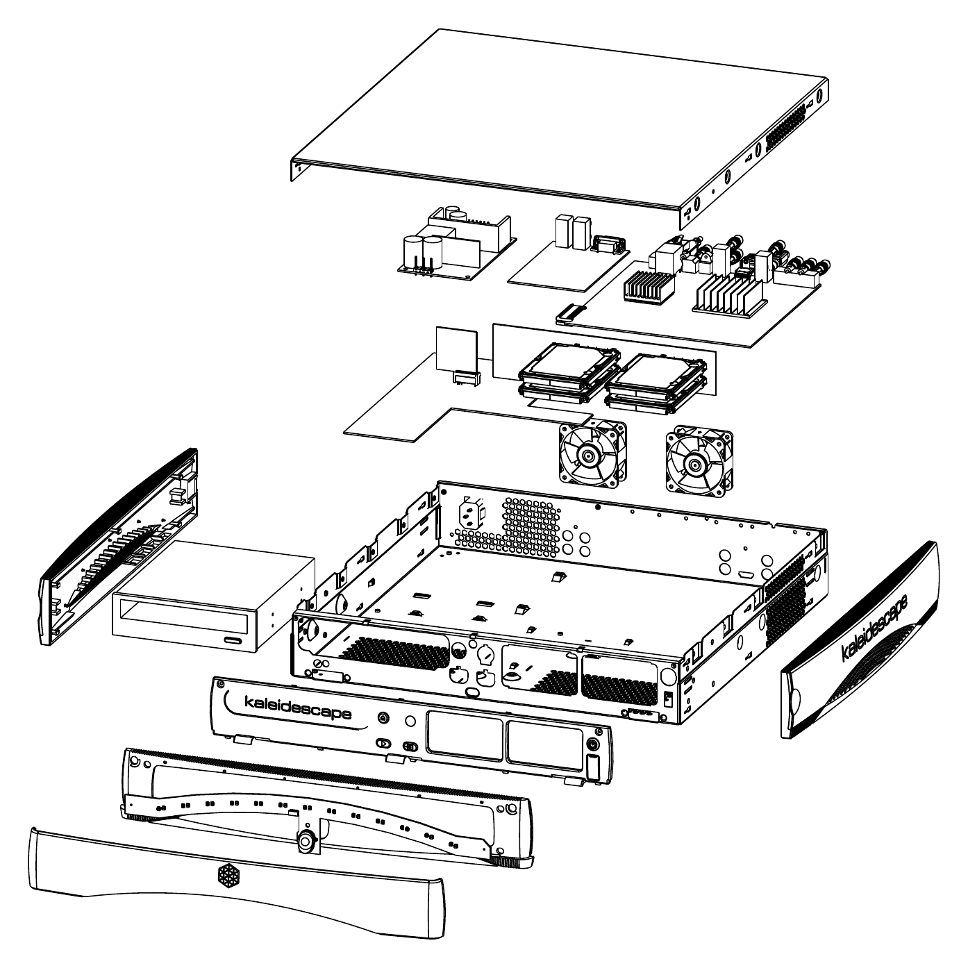
The exploded drawing made that negotiation concrete: enclosure parts, an optical drive, the drive stack, two fans and the boards had to occupy one coordinated arrangement. These were development views used to review the proposed packaging, not evidence that the configuration had been built or qualified.
Morpheus mechanical study
Reuse requirements
Making the interfaces work together
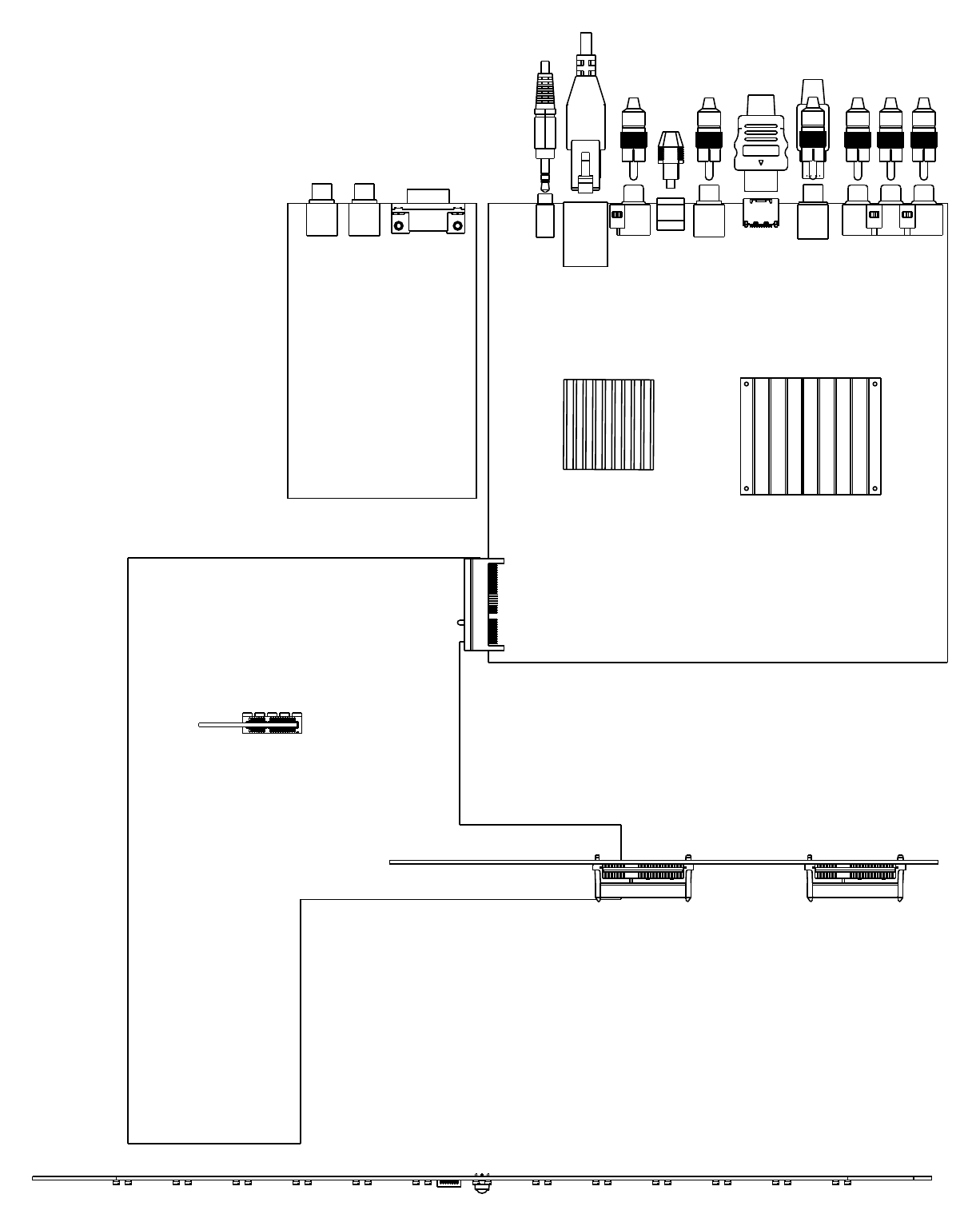
Early architecture discussions explored a reduced-cable arrangement. The drive cage could connect through a drive plane and an expansion card standing vertically in a board connector. The team also considered similar connections for the optical drive and fan assembly, while the front illumination board’s attachment remained undecided. The proposal joined mechanical support, electrical connection and assembly order at the same interfaces.
Common electronics did not make the rear panel common automatically. By November, Greg’s connector plan used a shared main board with different component populations and a separate board for serial control and extra audio zones. I checked the mechanical interpretation against the connector drawing and caught a reversed pair in its accompanying list. The drawing became the controlling reference for that correction.
A proposed direct-sale version introduced another physical distinction: it would omit the extra audio zones. Richard Lane asked me to work out a rear-panel blanking plate for the unused connector openings. His follow-up explicitly extended the proposal to Atlas Orpheus as well. The two programs therefore appear in the same correspondence, but their hardware histories cannot be treated as interchangeable.
Board and connector layout
Sharing layouts with the thermal design
Nathan’s thermal work affected where boards, fans and baffles could go. A November intake-baffle concept separated the two fan intakes to reduce recirculation through a stopped fan. Its intended benefit was continued cooling during a fan failure. That remained a proposed design behavior, rather than a demonstrated reliability result.
On December 1, I sent Nathan one-to-one top views of Morpheus and Pinata so he could arrange alternative baffles and fan configurations at the correct relative scale. His reply requested updated power-supply and board blocks, showing why a layout exchange needed to preserve the current component definitions as well as their outlines.
Nathan’s December presentation made the airflow proposal more specific. One fan would draw from the top and bottom of the drive cage, while the other would draw through its central channels and beneath the optical drive. An isolator would separate the paths. Nathan also proposed moving underside intake openings to the lower front edge, behind the door, to reduce recirculation when the enclosure sat in a rack or on a shelf. Those intended paths still depended on the space in my mechanical model and Vince’s board layout. They were proposals, not measured cooling results.
The December midplane discussion exposed a limit to commonality. Different distances between the main board and front illumination made a single rigid board difficult to reuse. Nathan proposed a flexible connection. I was working on the midplane outlines and agreed that a flexible interconnect could make a shared arrangement possible, while flagging the low current capacity of the proposed ZIF connections. Mechanical flexibility did not remove the electrical power constraint.
What the study established
The documented deliverables were a mechanical brief, review drawings, connector-fit work and packaging discussions shared with the electronics, thermal and manufacturing teams. The brief also listed the reliability and environmental work the product would need, including temperature, humidity, shock and vibration. Those requirements were still separate from qualification results.
The work continued as the Megalon product definitions became more specific. The December 3 hardware meeting, recorded by Rob Wudrick in a December 11 message, named Hydra as the integrated Ksystem and Titan as its direct-sale variant. On December 10, Nathan described his preliminary thermal layout as being for “Morpheus or Titan or whatever” and then circulated a Hydra layout. The Morpheus study was carrying into those system definitions.
The next recovered brief was titled Hydra/Titan. Its revision table records a third revision on December 16, 2008, incorporating feedback from the November review. It retained maximum KS-100 reuse and the distinction between required Blu-ray capability and a stretch slot-loading option. Its exploded view named the main board, auxiliary board, midplane and drive backplane, while several outlines were still marked to be determined. The brief gave the team a definite arrangement to review without treating every interface as settled.
That continuity still required changes to the physical arrangement. Nathan proposed reusing the entire drive cage, modifying the optical-drive bracket to let air flow underneath it, and adding an airflow-isolator baffle for the hard drives. The midplane and internal baffles depended on the actual spacing inside the enclosure, so he needed my 3D models to reach a final layout.
The January work made the electrical-to-mechanical handoff more explicit. Nathan’s system diagram, sent on January 13, distinguished a common main board from product-specific daughterboards, the Hydra/Titan drive backplane and the front glow-and-button board. I asked the hardware team to estimate the required signal lines, round up to an available connector pin count, and provide the manufacturer and series so I could assemble mechanical placeholders. Nathan was still gathering those definitions while considering a rigid-flex connection between the drive plane and main board. The exchange let us develop the packaging while the connections were still being defined.
At the January 15 hardware meeting, the team judged flexible cables more economical after discussions with Samtec. Nathan was to develop the system cabling diagram, while Greg would revise the connector diagram for Vince’s layout work and then my mechanical modeling. A later January message rejected the general midplane approach and required standard cables with two potential vendors. These were design and sourcing decisions; the cost advantage was a contemporary judgment, not a measured production saving.
The interface work continued into January. Vince checked Greg’s connector recommendations against the Mars and Titan/Hydra platforms from a PCB perspective, while asking me to review mechanical fit and specify the Ethernet/USB connector’s remaining position. Nathan’s January 23 cabling update set aside the broad midplane approach for the moment and considered a more limited connection between the optical drive, power supply and main board. Nathan’s attached comparison put the smaller-midplane tradeoff plainly: a board joining the optical drive, power supply and main board could remove cables and permit more preassembly, but its placement would differ between Morpheus and Apollo. Three cables offered a common arrangement. His note asked for both configurations to be modeled and discussed. The comparison’s assembly-step counts were assumptions, not a measured production improvement.
The contribution was a mechanical definition that the team could inspect and revise as the next designs took shape. The selected record does not establish the final qualification or shipment state of the November Morpheus arrangement.
Later interconnect and layout comparisons
The interconnect work continued in February. Nathan’s February 5 presentation separated the front-control and daughterboard links from the higher-speed connection to the drive backplane. The hardware meeting favored different cable and connector arrangements for those jobs and retained a second-source requirement. I supplied flexible-circuit manufacturer contacts as Nathan developed the options. The team was comparing cost, packaging and electrical requirements; these proposals did not yet establish a qualified production cable.
By March, Nathan was using physical layout mockups to compare reuse of the existing Apollo chassis with a new chassis made using soft tooling. His revised shared-board proposal added an unpopulated support section that could meet the existing mounting holes, then be removed for Titan and Mars. The Titan layouts showed the consequences for daughterboard space, power-supply position, fan inlet obstructions and the route of the front USB and power-button cable. Richard asked me to weigh in on the mechanical choice and pressed the team to compare the time needed for prototype chassis. The mockups supported that decision; they did not demonstrate which arrangement was ultimately built or its cooling performance.
A later prototype-definition record
The later Hydra interface drawings made those connections explicit in the mechanical layout. The July connector-placement sheet located the control/glow-board, drive-plane and button-board connections in plan and section; a companion sheet located the drive-plane LEDs. These were records of geometry being defined, without establishing a completed fit or reliability test.
The September Hydra glow-board drawing shows the interface work at a smaller scale. Its revision table records changes to the board outline and the addition of a VHB adhesive specification. A detail view marks two touch ribs in the front plastic that the board needed to clear. Board shape, attachment and neighboring plastic were being developed together, without the drawing establishing that the clearance had been verified in built hardware.
Later Hydra drawings show a further stage of mechanical definition. The chassis revision table records a change to its grounding stud and board standoffs as a release to PROTO2. A Blu-ray bracket revision is dated October 12, 2009 and also marked for PROTO2; a separate BTC drive bracket is marked for prototype release on October 8. These are defined drawing states, with EN approval initials. They do not establish when units were built or whether the thermal changes achieved their intended performance.
The selected record supports the design work and its continued development. It does not identify the November Morpheus arrangement with an unchanged later Hydra configuration, or establish final qualification, shipment or cancellation.