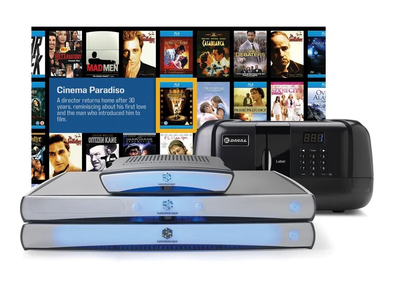
KPLAYER-300
Designing the complete player
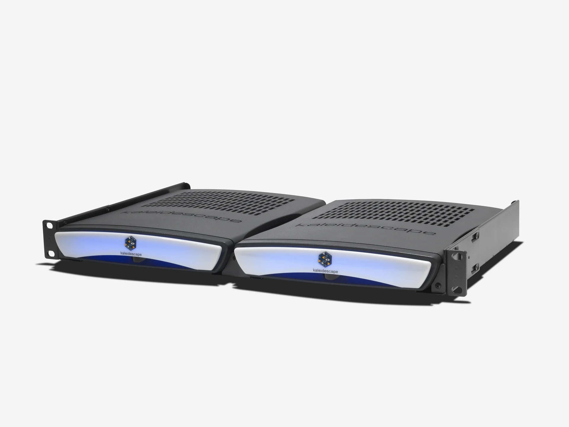
I designed and engineered Kaleidescape’s KPLAYER-300, known internally as Mercury. The compact player had to work in a rack shelf and behind a display, which we expected to be one of its most common installations.
My work spanned the enclosure surfacing and blinded vent pattern, the EMI liners and Acheson coating on the plastics, the glow board’s LED spacing and offset, and the main PCB’s mechanical layout and placement. I also designed the custom feet, fans, cooling system, fan grommets and mounting hardware.
The mechanical interface drawings brought the enclosure and electronics together: board mounting points, connector openings, component clearances and the glow board’s physical envelope. Separate parts handled the translucent front screen, the IR window and the fan mounting bracket. These details had to work together within the compact housing.
M300 product views

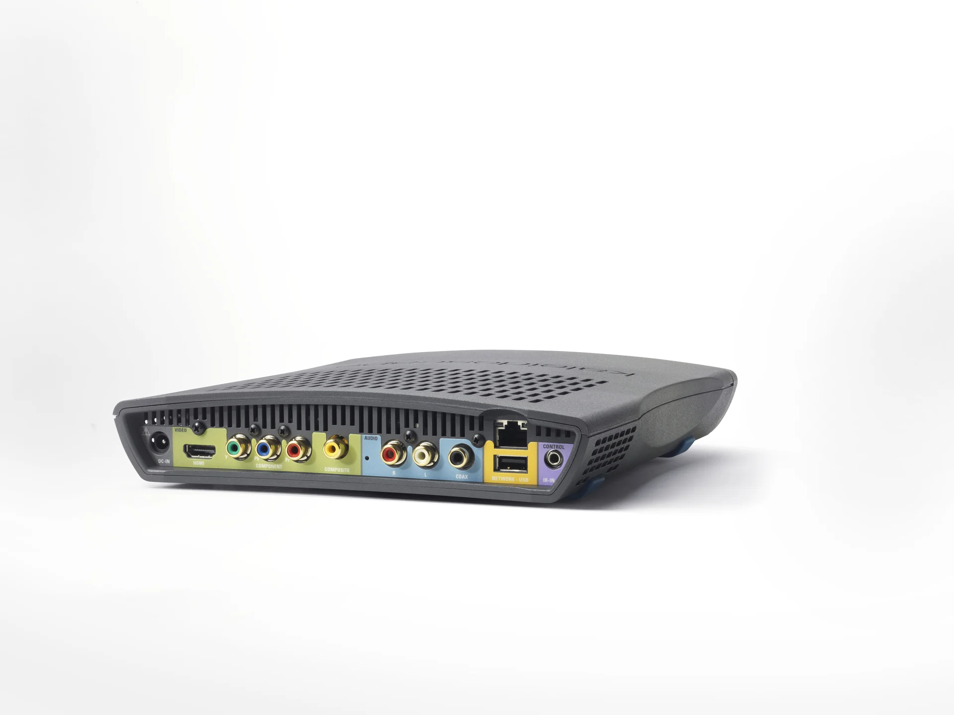
Openings without exposing the interior
The enclosure used a blinded, labyrinth vent pattern. It provided ventilation while concealing the interior, making the openings part of the player’s appearance as well as its cooling system. The Acheson coating on the plastic parts tied the metallic liners together into an integral Faraday-cage shield.
Mechanical architecture
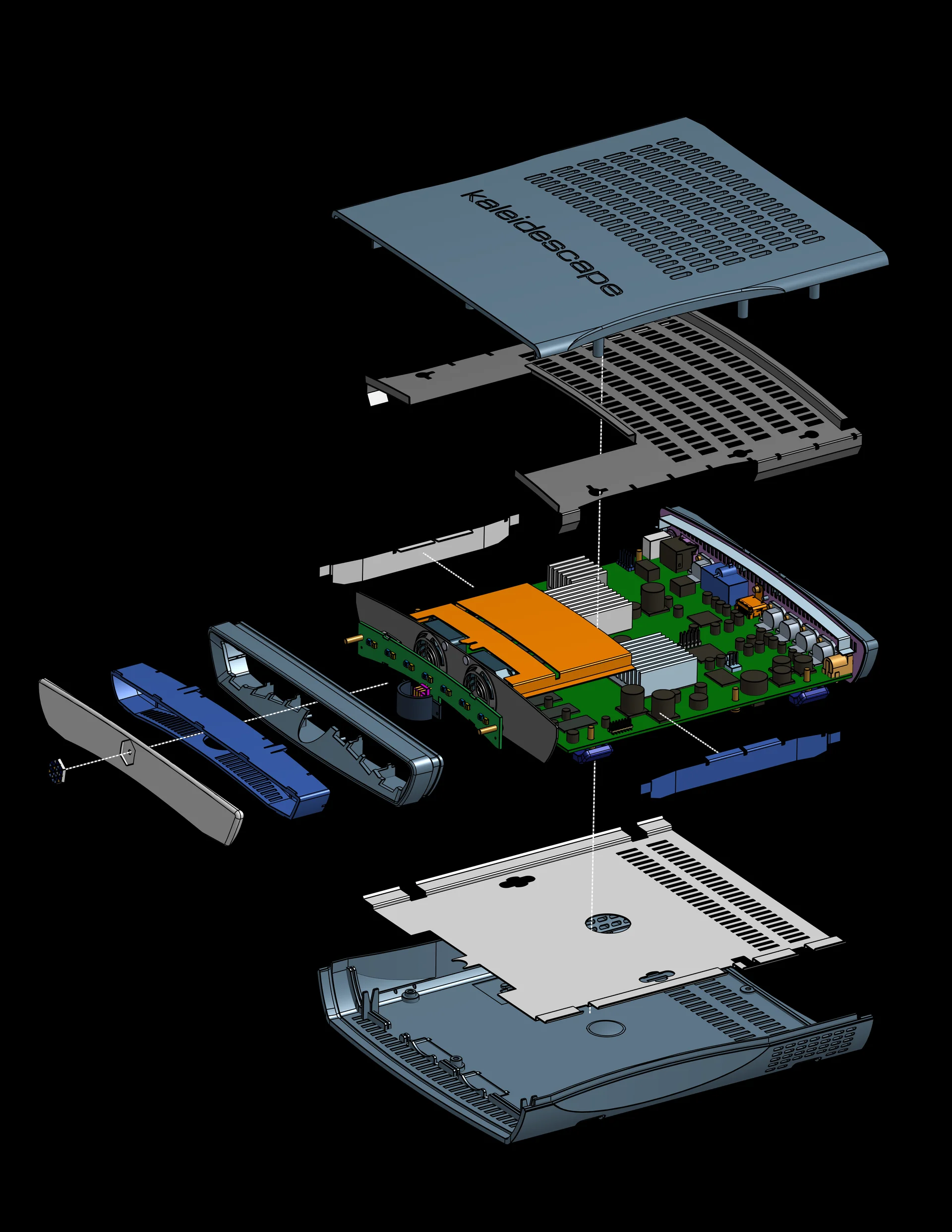
A continuous shield inside a plastic enclosure
That continuity depended on the interfaces. On June 9, 2008, Greg Curry reported inconsistent coating in the grooves and loose fits around the fan bracket and rear panel. On July 7, he separately found inner vent surfaces electrically disconnected from the surrounding coating. The drawings needed to communicate both the coating and the places where the supplier should measure resistance. The masking illustrations called for conductive coating through the front and rear mating grooves while keeping it out of view through the exterior vents.
I worked with Greg and Argyle to turn those observations into drawing changes. During the July plastics review, we considered crush ribs to improve contact at both the fan and rear-panel grooves. The subsequent clarification limited the base change to the fan groove. Greg also redirected the resistance checks into the inner vent rows, where the earlier sample checks had missed disconnected coating.
The coating process continued to evolve. Early drawings specified Acheson Electrodag 550; in July I requested 599-Y2000 and Gabe returned updated drawings. The accompanying data sheets describe different nickel and copper coating systems. The retained revision 4 top and base drawings still differ on that callout, so they do not establish one final coating specification for every production part.
Tuning the blue glow and isolating the fans
The same enclosure had to meet Kaleidescape’s blue-glow identity. I tuned the LED spacing and offset, while the hardware team evaluated LEDs and electrical drive settings. In a June 12 comparison with Apollo, Sean Paul recommended retaining the current resistor values and default setting, and Greg agreed. The elastomeric fan grommets addressed another part of the experience by isolating vibration and reducing noise.
Bezel illumination

Reviewing the enclosure as a system
The mechanical change sheets brought cosmetic and functional issues into the same review: highlight-line alignment, texture, vent fill, short bosses, panel fit, coating coverage and fan-grommet compression. I coordinated updated drawings with Argyle and the manufacturing team so that the supplier’s parts, inspection instructions and released files could be compared against the same design intent.
The build also depended on approvals outside the drawing set. The June schedule was explicitly tentative. A July 1 shortage list still carried mechanical-part approvals, unreleased labels and packaging details, alongside permission to obtain quotes and place orders for mounting brackets. Those entries tracked different stages of preparation; an approved order did not establish that a part had arrived.
The feet exposed another manufacturing tradeoff. An earlier foot drawing specified Santoprene 211-64; in July I confirmed the softer 201-64 material and blue color, then worked through adhesive size and primer application with the supplier. The softer parts stuck in the mold. Weddy proposed small pullers to retain them on the core side during molding, and corrected our initial description of those features as ejector pins.
Production preparation did not advance as one clean revision. On July 22, Weddy reported scrapping 400 top shells because of a small central dimple and sending a 200-set plastics lot to Proworks with modified tops and unmodified bases. The next day, Michael Clader reported inspecting that shipment with Sandra Twist and approved further coating and painting. Those were supplier-part decisions, separate from finished-player delivery.
Power supplies and the rear-shield interface
Initial power-supply problems forced us to evaluate several types, with different bodies, connections and cable routes to accommodate. A measured sample did not always match its supplied dimensions. Ault was the team’s stated choice in early June, while alternate supplies and their mounting brackets remained part of the development work.
During EMI testing in June, Greg Curry and Adrian Fung reported a LAN-conducted emissions pass after isolating the Ethernet connector from the metal rear plate. Gabe Cohn supplied revised shield CAD, and I compared the old and new geometry as the clearance requirement moved into the mechanical design. The reported pass applied to the configuration under test.
The broader test program continued after that fix. June meeting minutes still described immunity and CSA work in progress. July 2 minutes reported EMC completion for Mercury with the Ault supply while alternate supplies remained under evaluation. By July 16, the minutes reported CSA completion and receipt of its reports. The July 23 update repeated that status and recorded a verbal EMC pass with the written report still due. These were contemporaneous progress reports; the underlying reports would be needed to identify the exact certified configuration.
Changing the mounting hardware
The mounting hardware also evolved. An existing screw protruded too far, while shortening its thread raised manufacturing concerns. I developed replacement options and updated the design files and KPLAYER-300 BOM. July and August drawings show an inner-screw arrangement followed by a custom clinch stud, even where the revision label stayed the same. Michael Clader handled record locking and ECO follow-up, and Amiee Rooney asked to keep the existing hardware available while the replacement went through prototype review.
Mounting and rack installation
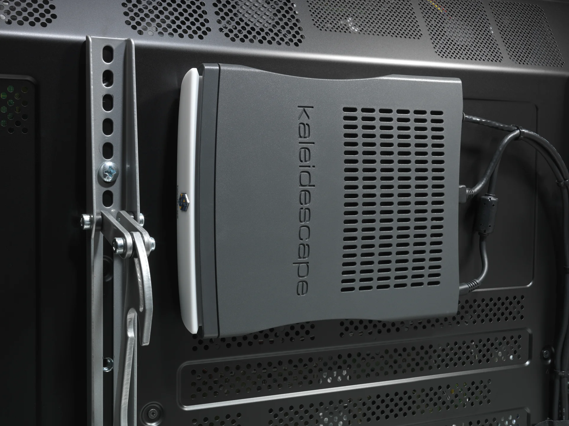
Testing the required installation
Installation introduced questions beyond whether the bracket fit. The team planned safety testing in both vertical orientations even though the documented installation would show the cables upward. I clarified fastener sizes for the brackets sent to the lab. Later supplier and assembly questions required the intended mating parts and release reference to be made explicit.
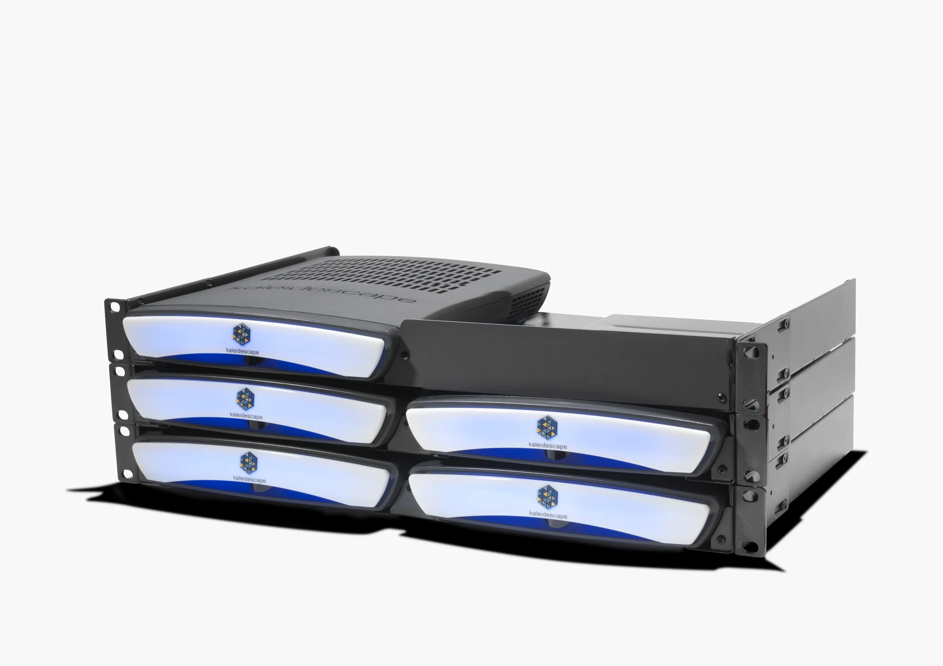
The rack shelf had its own development schedule. In June I prepared a 10-inch-deep prototype design with single- and double-player arrangements. July prototype drawings used thicker sheet metal and formed ribs, and the team approved a 25-unit prototype build. A deeper arrangement with one power brick and a Y-cable remained a separate, hypothetical option. It was not the configuration being built for the current shelf.
The thermal setup mattered as much as the shelf geometry. Nathan Forster credited Ali Hussaini with observing that airflow in the thermal chamber could cool the players more than a real rack would. Nathan then proposed testing a populated rack outside the chamber.
The case and shelf posed different thermal questions. Data Greg circulated on August 11 compared two modified case configurations: both had extra side vents, while one also had ribs removed and two rows of bottom vents added. The combined change lowered the recorded sensor temperature, but the comparison did not isolate the effect of bottom vents. Greg was also concerned that the raised shelf would obstruct those openings.
Nathan prepared shelf prototypes with taped cardboard patterns to examine vent alignment. Later in August, he reported adequate thermal margin and no component-temperature difference between the shelf arrangements he tested. That supported considering a simpler shelf; it did not make the player’s own case vents unnecessary.
The August shelf review also addressed handling: reversing the slide direction to resist accidental movement, adding a securing screw, stiffening the rear edge and aligning the rack ears. Rob Wudrick’s August 22 notice reported the KSHELF-300 BOM released in Arena. Supplier questions afterward still required the welded assembly and its component drawings to be clarified.
The installation drawings had to communicate the complete stack. After a dealer interpreted the height as accumulating with each shelf, Linus Wong requested a stacked view and I supplied a revised drawing candidate. The review covered clearance above the top shelf as well as the individual dimensions.
From KPLAYER-300 to M300
KPLAYER-300 quickly evolved into the M300 during production. The physical products were virtually identical; the processor architecture changed to support Blu-ray playback. The mechanical design carried forward as the media platform evolved.
System context